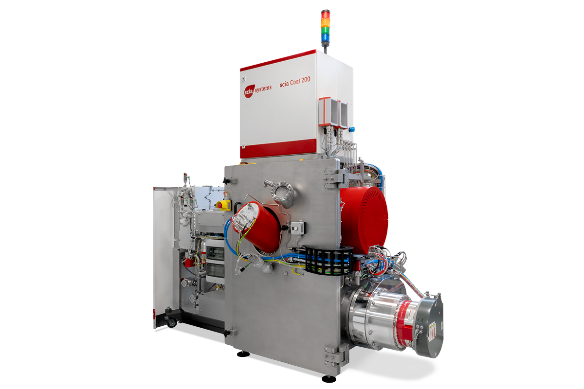
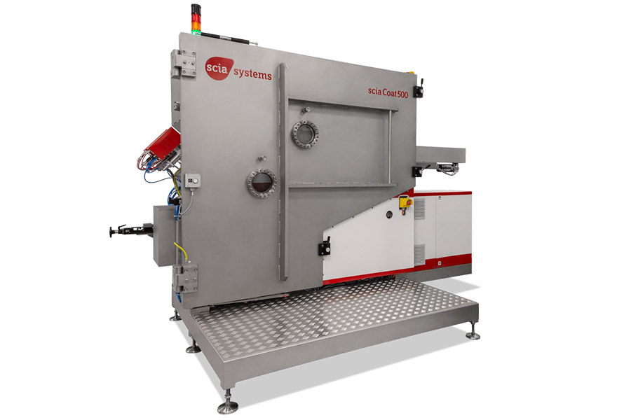
The scia Coat 200 and 500 are ion beam sputtering (IBS) systems designed for coating homogeneous, smooth, dense, and defect-free films on substrates up to 200mm and 500mm, respectively. In-situ monitoring ensures excellent process stability.
An optional secondary ion beam source can be added on for substrate pre-cleaning, and/or assisting during deposition. This configuration is known as dual ion beam sputtering (DIBS).
Principle:
scia Coat 200 IBS
scia Coat 200 DIBS configuration
scia Coat 500 IBS
scia Coat 500 DIBS configuration
Both Coat 200 and 500 systems operate on the IBS principle, in which the primary source sputters material from target to the substrate. Both systems also have the option to upgrade to DIBS configuration.
Features and Benefits:
Both Coat 200 / 500:
- Excellent uniformity by (substrate rotation and tilt – Coat 200) and (linear movement – Coat 500)
- Up to five / six (Coat 200 / 500, respectively) water-cooled target materials on a rotational holder for in-situ change
- Recipe controlled multilayer deposition with quartz crystal oscillator and/or optical thickness monitor (OTM) and test glass changer
- Vertical or face-down substrate orientation for minimized particle load
Coat 200
- Direct wafer handling or adaptation to variable substrate sizes with carrier handling
- Equipped with a 350 mm ion beam assist source is also usable for ion beam etching processes
Coat 500
- Controlled movement of linear axis system for gradient coating or surface error correction
- Optional substrate heating up to 250 °C to optimize film stress
Applications:
- Optical coatings for high- and anti-reflective layers, dielectric layers, bandpass and notch filters
- Multilayer films for magnetic sensors (GMR, TMR, spintronics)
- Multilayer films for optical filters, X-ray mirrors and synchrotron mirrors
- Films with property gradients (Göbel mirrors)
- High laser damage threshold coatings
- In-situ preprocessing of substrates (etching, cleaning, smoothing)
- Ion beam smoothing
- One-dimensional ion beam figuring
- Deposition of precise, homogeneous, smooth, dense, and defect-free dielectric and metal layers
Transmittance and reflectivity diagram of a high-reflective mirror. Deposition of quarter-wave stack consisting of tantalum(V)-oxide and silicon dioxide for high-reflective mirror @ 630 nm. Reflectivity > 99.9 % and transmittance 15-20 ppm

X-ray reflectivity measurement and fitting curve of a [C+Ni]80-multilayer stack. Visibility of 4th order Bragg peak shows the excellent repeatability of single layer thicknesses.
Technical Specifications:
| Coat 200 | Coat 500 | |
|---|---|---|
| Substrate size | up to 200mm dia. | 500mm x 300mm |
| Substrate movement | Rotation: 5-20 rpm | Linear: 0.1mm/min – 15 mm/s Rotation: up to 300rpm (max 300mm dia.) |
| Substrate Tilt | 0° to 160°, in 0.1° steps | N/A |
| Substrate holder | Water-cooled, helium backside cooling contact | Optional: substrate heating up to 250°C (film stress optimization) |
| Ion beam sources | Sputter source: 120mm circular RF source (RF120-e) Assist source: 120mm circular RF source (RF120-e), or, 350mm circular RF source (RF350-e), or, 218mm circular microwave ECR source (MW218-e) | Two 380 mm linear microwave ECR sources (LIN380-e) |
| Neutralizer | Filament neutralizer (N-DC), or, RF plasma bridge neutralizer (N-RF) | Filament driven plasma bridge neutralizer (N-DC) |
| Target holder | Target drum with tiltable and water-cooled targets: up to 5 (each max. 220mm dia.), or, up to 4 (each max. 300mm dia.) | Target drum with tiltable and water-cooled targets: up to 6 (each max. 400 mm x 200 mm) |
| Typical deposition rates | Ag: 35 nm/min Al: 10 nm/min Si: 15 nm/min Ti: 8 nm/min Al2O3: 15 nm/min SiO2: 20 nm/min Ta2O5: 15 nm/min TiO2: 6 nm/min | Si: 10 nm/min |
| Uniformity variation | ≤ 0.5 % (σ/mean) | ≤ 0.5 % over 200 mm dia. (σ/mean) ≤ 2.0 % over 500 mm x 300 mm (σ/mean) |
| Base pressure | < 5 x 10⁻⁷ mbar | < 5 x 10⁻⁸ mbar |
| System dimension (W x D x H) | 3.10 m x 1.70 m x 2.40 m single chamber with cassette handling (without electrical rack and pumps) | 3.30 m x 1.70 m x 2.00 m (without electrical rack and pumps) |
| Configurations | Single chamber with single substrate load lock, or, Single chamber with cassette handling, or, Cluster system with cassette handling | Single chamber Optional: single substrate load lock for substrates up to 200 mm dia. |
| Software interfaces | SECS II / GEM, OPC | SECS II / GEM, OPC |